|
|
This page is still under construction,
Click
here to trouble shoot Decoders
Clike
Here to Trouble shoot Encoders
Signal
Ground/common: The input circuit signal ground, must be connected
to Pin 1 on the green input connector..
On the board, there is
NO connection between chassis/earth ground and Signal/common ground. Do
not install one.
On the DMX data cable,
there should be NO connection between the shield/XLR shell earth ground
and the signal/common ground. Do not connect these together.
Termination:Northlight’s
Decoder does not contain a terminating resistor. It is up to the user to
determine the termination requirements. If the Decoder board is the last
one on the DMX link a 120 terminating resistor can be installed on the
green DMX input connector, across pins 2 – 3.
It is possible to “over
terminate”. In other words make sure there is only 1 terminator on the
end of the DMX line. Some
devices have internal terminators,
double check the settings.
Red Power LED: Use a multimeter on the screw terminals of the green input power connector to double check the input power. If the red LED is out, and the board is getting power, the power supply may be defective.
Green
Signal LED: If the green LED is blinking, there is no valid signal
present.
If the LED is on, but
dim, and the receiver is not responsive, try to reverse the DMX signal
wires. A valid signal will produce a steady bright LED.
Double check the input
ground connections. Make sure there is no connection between earth ground
and the signal common/ground.
No output:
Check the signal wires as noted above.
Be sure the address is
set to a valid address. The Decoder start address should not be higher
than the highest address received. On the mini DIP switch, up position
is off. Down is on.
Erratic
output: This problem can be hard to track down. First check
the input signal integrity. There should be signal present on both Data
lines. Reverse the connections.
Another potential problem
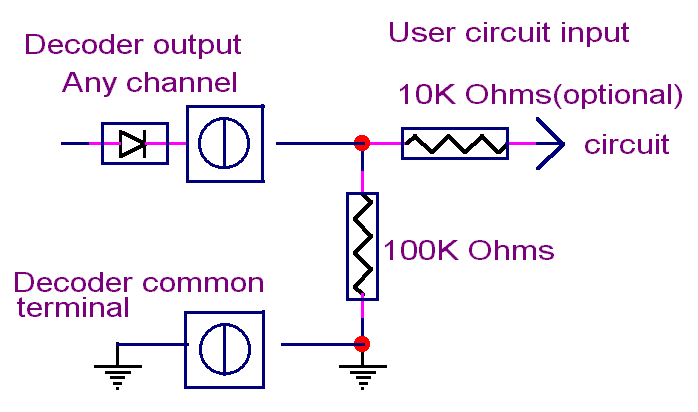
here is the user circuit interface. It may be necessary to
install a 47K to 100K resistor between the Decoder board output and the
user circuit ground(NOT chassis/earth ground). This is usually already
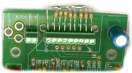
there in most situations. A typical arrangment is shown schematicaly on
below/left. The photo shows a typical resistor arrangment using 100KOhm
1/8 watt resistors. !/4 watt resistors will also align correctly with the
connector.
 |
 |
Misc:
Good
solid connections are a must. The micro screw terminals provide good connections.
However the screws can be stripped by over tightening.
DMX512 signal wires should
be twisted together all the way to the connector.
It is recommended that
a separate transformer be used to power the Decoder board. Occasionally
unexpected problems can occur if power is ”borrowed” from another source.
Small wall wart transformers work well for this application.
Basically the board is plug and play. There are no user adjustments. When all connections are properly made, a DMX signal, porportional to the input voltage will be present at the output pins.
Signal
Ground: The input circuit signal ground, should be connected first.
On the board, there is NO connection between chassis/earth ground and Signal/common
ground. Do not install one.
On the DMX data cable,
there is NO connection between the shield/XLR shell earth ground and the
signal/common ground. Do not connect these together.
Termination:Northlight’s Encoder does not contain a terminating resistor. If It is determined that a terminator is required, a 120 terminating resistor can be installed on the green DMX input connector, across pins 2 – 3.
Red Power LED: Use a multimeter on the screw terminals of the green input power connector to double check the input power. If the red LED is out, and you know the board is getting power, the power supply may be defective.
Green signal LED: On the 32 channel encoder only. When the voltage on any of the input channels is over .50 VDC the LED will turn on.
No output:
Be sure the address is set to a valid address. The Encoder start address
should not be higher than the receiver start address.
Check for backwards DMX
signal connections.
If only some inputs generate
DMX, check the connections and verify the input voltage at the screw terminals.
Erratic
output: This problem can be hard to track
down. First check the input signal quality and voltage. If
the input voltage goes over 10 VDC, the output will be 0 for that channel.
Another
potential problem here is the user circuit interface. It is may be that
a 10K to 100K resistor be connected between the encoder board input and
the user circuit ground. This is usually the case when there is a diode
on the user circuit output. This is shown schematicaly on right.
The input maximum voltage is 10 VDC. Higher voltages may damage chips.
Misc:Good
solid connections are a must. The micro screw terminals provide good connections.
However the screws can be stripped by over tightening.
DMX512 signal wires should
be twisted together all the way to the connector.
It is recommended that
a separate transformer be used to power the Encoder board. Occasionally
unexpected problems can occur if power is ”borrowed” from another source.